A recent project I worked on involved retiring Citrix ADC instances off of end-of-support Citrix SDX hardware, and migrating the config to new ADC instances hosted in VMWare on Cisco UCS hardware. A recent project I worked on involved retiring Citrix ADC instances off of end-of-support Citrix SDX hardware, and migrating the config to new ADC instances hosted in VMWare on Cisco UCS hardware. Initially, I didn’t think this was going to present any issues, as it’s still ADC virtual instances running on a hypervisor (now ESX as opposed to XenServer). What I didn’t expect was that UCS would present me with a big hurdle to overcome.
In my organization, we have historically deployed UCS domains in a straightforward and systematic manner. For each ‘environment,’ we deployed a pair of UCS fabric interconnects with network, compute, and storage specific to that environment. An ‘environment’ would be a specific subset of the infrastructure dedicated to a certain purpose. Some examples of environments could be:
- Production
- Pre-production/Dev
- DMZ
- PCI
These could be broken down even further for specific platforms inside of those environments such as VMWare, Linux, VDI, etc. If you don’t have UCS currently, and are planning on it, your organization will ultimately decide how to deploy UCS domains based on need, and, of course, budget.

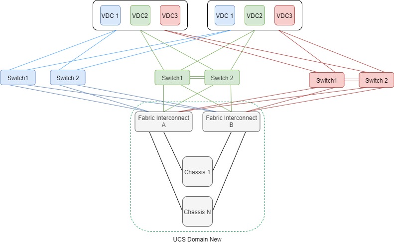
On the Citrix side, The SDX appliances run ADC virtual instances that support multiple environments, as the need and cost doesn’t necessitate having an SDX pair for each individual environment. The switchports configured for the SDX connections trunk all necessary VLANs, and the ADC instances are mapped to those interfaces based on their environment.

As you can see, there’s a fundamental difference in connectivity between UCS and SDX based on the images above. The UCS domains only connect to their discrete environment’s layer 2 infrastructure, whereas the SDX appliance connects to all layer 2 environments. In my specific case, we didn’t have any UCS virtualization in the environments, which meant new virtualization infrastructure was needed to support the migration. Given our current method of deploying UCS, if I have three different environments to migrate I need three new UCS domains complete with fabric interconnects, chassis, blades, etc. This wasn’t going to be possible given time and budget constraints. The answer seemed simple…build one UCS domain and connect it to all three environments, very similar to how the SDX is connected today. That’s 1/3 the equipment, licensing, implementation tasks, and support costs. WIN…WIN…WIN…and WIN!
We We moved forward with deploying a new UCS domain, and connected it exactly how I planned. I deployed the new ADC instances after VMWare was configured, and things were looking good.
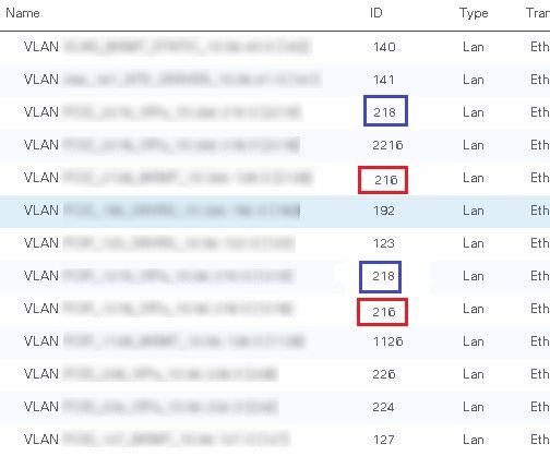
The UCS config to accomplish this was pretty straightforward. I defined the VLANs like I normally would, and also used VLAN groups to create logical groupings in UCS Manager for the three environments. These groups were then assigned to the VNICs in the service-profiles, and assigned to the servers. I was able to create different VLAN names with the same VLAN ID in UCS Manager. The reason for the VLAN overlap was because I used a consistent VLAN ID for management, and VIPs across all environments for simplicity…or so I thought. While being able to add the same VLAN ID twice in UCS manager seemed strange, the overlapping VLANs were in different VLAN groups. I didn’t give it much thought as there was logical separation, so I continued on.

I checked back a few hours later to see how things were, and I noticed that some of my ping tests to the ADC instances weren’t working anymore. There was also strange behavior with pinging VIPs on the ADCs that would either fully timeout or skip every other packet. Also, some HA heartbeats between ADC instances on different ESX hosts were failing. Hmm, that’s not what I expected.
I started checking the ARP caches on the upstream switches, and saw a variety of complete, and incomplete ARPs. I cleared the ARP caches, shut/no-shut interfaces, and tried pinging again. This time all of the ARPs were incomplete. Ugh, something isn’t right. I spent several hours troubleshooting layer 1 and layer 2 on the ADC instances, and the upstream switches. ESX didn’t appear to be an issue as all the VLANs were configured correctly using multiple vswitches to overcome the overlapping VLANs. We had also previously defined a new port-group with a VLAN tag of 4095 to trunk VLANs through to the ADC instances, but that wasn’t causing the strange connectivity either.
After coming up empty, I opened a Cisco TAC case. After reviewing the details with the TAC engineer, she stated that I was deploying a “disjointed layer 2” UCS topology, and there were considerations that needed to be looked at in order to get this working correctly. I explained that I was concerned when I was allowed to configure the same VLAN ID for multiple VLAN definitions, but since I was allowed to configure it, I didn’t give it much thought. Turns out my spidey senses were correct. While it’s perfectly fine to configure VLAN overlap in UCS manager, and the fabric interconnects understand the VLAN grouping logical separation, this is not the case when traffic is forwarded down to the chassis level. Everything on the network up to the fabric interconnects is a traditional layer 2 network, so things like spanning-tree, broadcasts, and multicasts act like you would expect. Once that traffic is in the fabric interconnects, it’s a totally different world.

Fabric interconnects can operate in one of two Ethernet switching modes: End-Host mode, or Switch mode. Switch mode is traditional Ethernet switching. The fabric interconnects run spanning-tree to avoid loops, broadcast and multicast traffic is handled normally. End-Host mode allows the fabric interconnects to act as an end host on the network, representing all host behind it using vNICs. These vNICs are pinned to uplink ports which allows connectivity. Spanning-tree is not run in this mode, and a single port (or port-channel) on each fabric interconnect is chosen to be the broadcast, and multicast receiver for a VLAN. This port is know as the Designated Receiver, and was the crux of my issue. Here are some links with more info how to deploy disjointed layer 2 networks, and on end-host mode.
- Deploy Layer 2 Disjoint Networks Upstream in End Host Mode
- Cisco UCS Manger Network Management Guide – LAN Connectivity (Release 4.0)
The best way to verify which port is the designated receiver for a VLAN is to run the command ‘show platform software enm internal info vlandb id <vlan ID>‘ from the NX-OS command area of the fabric interconnects. Based on the output below you can clearly see that there are two port members for VLAN 216 (Po10 and Po20), and Po10 was chosen as the designated receiver.
FI-A(nxos)# show platform software enm internal info vlandb id 216

vlan_id 216
-------------
Designated receiver: Po10
Membership:
Po10 Po20
There are two port-channels that are members for VLAN 216. These ports are the fabric interconnect uplinks to two different environments. UCS Manager has chosen port-channel 10 to be the designated receiver, so any ARP broadcasts from either environment will be received on port-channel 10. If the ARP is from VLAN 216 on the environment connected to port-channel 20, the ADC instances with that VLAN 216 trunked to them won’t receive the ARPs. My earlier troubleshooting effort (clearing of the ARP caches, and shutting/no shutting the interfaces) caused the designated receiver to change. Sometimes this worked in my favor for what I was testing, at that point, but it wasn’t working consistently for both environments.
At this point I had three options:
- Renumber the VLANs to be unique between all three environments
- Research private VLANs as a possible option
- Deploy ACI
Well, right off the bat I eliminated ACI, as it’s not a feasible option right in this case. So that left me with renumbering VLANs, or look into private VLANs. Researching more, I found the following except from the UCS Manager Network Management Guide Release, 4.0:
Overlapping VLANs Are Not Supported
Cisco UCS does not support overlapping VLANs in disjoint L2 networks. You must ensure that each VLAN only connects to one upstream disjoint L2 domain.
Cisco UCS Manager Network Management Guide, Release 4.0
And there it was. The excerpt that brought the last four hours to a head. I had only one option moving forward, and that was to renumber the VLANs in the environments to be unique among all environments. Fortunately, I only had three overlapping VLANs across two environments, and the environments were not very large. I went to work changing VLAN names, numbers, and configs on trunks, access ports, etc. In my case, the whole process took just over an hour. Not terrible.
A quick check of the designated receiver config on the fabric interconnects showed the results I expected. Testing ARPs, pings, HA, and all other network connectivity checks all worked perfectly.
FI-A(nxos)# show platform software enm internal info vlandb id 1216

vlan_id 1216
-------------
Designated receiver: Po10
Membership:
Po10


FI-A(nxos)# show platform software enm internal info vlandb id 2216

vlan_id 2216
-------------
Designated receiver: Po20
Membership:
Po20
My biggest takeaway from this experience was that unique VLANs are needed when connecting disjoint layer 2 environments in UCS using end-host mode. It would be interesting to deploy a UCS domain in switched mode, and test a disjointed layer 2 design to see how it functions. If anyone has experience with this, feel free to enter them in the comments, or reach out to me on Twitter.
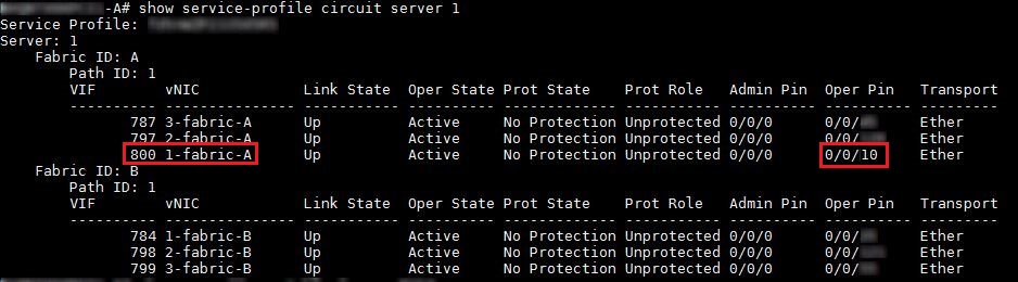
One extra note that I didn’t include above…I did have to do some digging on the fabric interconnects to verify layer 2 information for the ADM instances. I’ve included some additional commands, and output that shows how I verified the MAC, virtual port, and server service-profile mappings in UCS.
The MAC address on my ADM instance was 00:00:5e:00:01:64. From that I was able to verify the virtual ethernet (Veth) interface the MAC was associated to, and how that was pinned to port-channel 10.


Hello Chad thanks for your post, tomorrow I will try this configuration in a Live environment, the last attempt did from one of my partners the production connectivity was lost, So tomorrow is my call, before any changes I will use the commands you shared on this post
LikeLike